Rebar Caps Case Study
Investigating the Installation and Reusability of Steel Reinforced Rebar End Caps
Submitted by:
Marllon Daniel Cook, Ph.D.
Eryca Contractor-Janitz
Construction Engineering Technology Program
College of Engineering, Architecture, and Technology
Oklahoma State University
Stillwater, Oklahoma

August 31, 2023

1.0 Introduction
Steel reinforcement also known as “rebar” is used in reinforced concrete structures [1,2]. During the construction process of building reinforced steel concrete structures, the ends of vertical rebar can commonly be temporarily exposed. For example, a strip footing for the foundation of a building usually has vertical rebar installed to tie this footing into the concrete slab on the ground. Before this vertical rebar is bent and tied into the footing, these vertical rebar ends create safety hazards without proper protection [1,3]. These ends of the rebar not yet tied off can create a variety of safety hazards such as tripping, falling, and impalement of a worker [3,4]. The sharp ends of the rebar can also cut workers. OSHA 1926.701(b) states “All protruding reinforcing steel, onto and into which employees could fall, shall be guarded to eliminate the hazard of impalement” [3]. According to the Occupational Safety and Health Administration (OSHA) at the Department of Labor, there has been 69 incidents occurring from rebar impalement between 03/07/1984 to 03/07/2021 [4]. In these 37 years, there were 16 fatalities out of the 69 reported impalement incidents. Figure 1 shows 23% of rebar impalement incidents reported resulted in a fatality. Every year 1.86 accidents are reported from rebar impalement.

Figure 1 shows safety statistics for rebar impalement from 1984 to present.

Figure 2 shows rebar end caps on the end of vertical rebar installed on a footing of concrete floor.
As a solution, rebar end caps have been developed and used to help reduce the job hazards associated with the installment of rebar on sites shown in Figure 2. The rebar end caps have become an essential safety measure when working with exposed vertical rebar. The functionality of rebar ends caps is intended to be used temporarily until the ends of these vertical rebar can be properly tied off to other rebar. These plastic caps are installed onto the end of the rebar. The common vibrant coloring, usually orange or yellow of these rebar end caps helps indicate awareness of the rebar itself for workers passing by or working in that area. Once the vertical rebar is ready to be tied back into the reinforcement, these rebar end caps are removed, placed in a container, and stored until they can be reused again [1, 5].
(a)
(b)
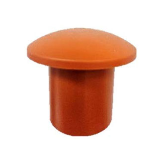
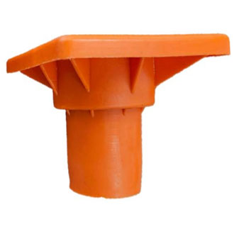
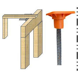
Figure 3 shows (a) mushroom style rebar end cap and (b) impalement style rebar end cap.
Probably the two most popular types of rebar end caps are mushroom style rebar end cap as shown in Figure 3 (a) and impalement style rebar end cap as shown Figure 3 (b). It is important to point out that not all rebar end caps are designed to have the same performance. The shape, size, and other design features play a key role in how these rebar end caps behave [6]. Some rebar end caps provide only basic protection from scratch guard while others protect workers from potential impalement. In addition, some rebar end caps can only be secured on a limited rebar size range such as #3 to #7. But others can securely fit on a broader range of rebar bar sizes such as #4 to #11[1, 5, 6].

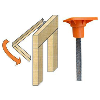
Figure 4 shows mushroom style rebar end caps being used on a swimming pool project.
1.1 Mushroom Style Rebar End Caps
Small round rebar end caps known as “mushroom caps” or “scratch caps” as shown in Figure 3(a) can be found in light residential applications such as a house foundation, retaining wall, or swimming pool. These small round rebar end caps can provide scratch protection due to the smooth and rounded design of the cap to surround the top of the vertical rebar. Typically, these mushroom rebar end caps can only be secured on a limited rebar size ranging from #3 to #7. However, these mushroom caps do not meet the commonly referenced impalement guidelines set by OSHA within the state of California [5, 6]. As shown in Figure 4, these workers are placing concrete in an area where vertical rebars were installed with mushroom caps. These mushroom caps do not conform to the impalement portion required in the CAL/OSHA standards. In other words, if a worker falls on a vertical piece of rebar, the thin plastic mushroom caps on this rebar may not protect the worker from implement and the end of the rebar penetrates through the rebar end cap and possibly enters the body of the worker.
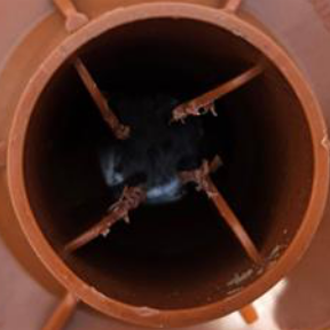
1.2 Impalement Rebar End Caps
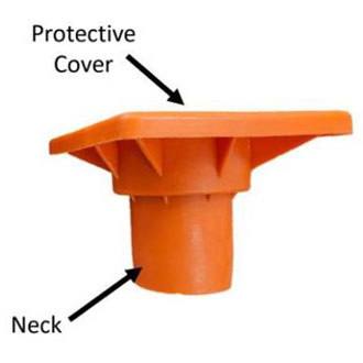
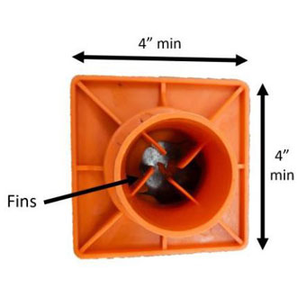
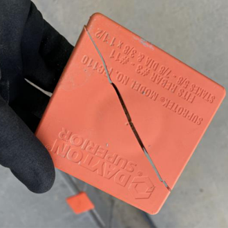
Another type of rebar end cap has been used specifically for impalement precautions [5]. These impalement protective rebar caps are commonly in the shape of a square, circle, or trough type top [6]. A traditional “square-end cap” is shown in Figure 5. These caps are composed of a neck, internal fins, and a top protective cover. Projects with potential impalement hazards should use an impalement rebar end cap. The purpose of these impalement rebar caps has been to protect a person from falling onto the exposed rebar and becoming impaled. To be classified as an impalement protection rebar end cap, this rebar end cap must meet all the qualifications on the CAL/OSHA Regulations in Title 8 under Section 1712 “Requirements for Impalement Protection” [5]. These detailed impalement standards were written from the state of California Division of Occupational Safety and Health also known as “CAL/OSHA”. To be Cal/OSHA approved for impalement protection, these rebar end caps must pass all the state of California OSHA requirements including the CAL/OSHA Drop Test. Some of these requirements are fairly straightforward. As shown in Figure 5 (b), CAL/OSHA impalement caps for a square end type are required to be designed with a square top dimension of at least 4 inches.
(a)
(b)
Figure 5 shows (a) side profile and (b) underneath of an impalement square end rebar end cap.

(a) (b) (c) (d) Figure 6 shows the steps of the Drop Test being conducted on an impalement cap[5].
1.2.1 Drop Test
Yet, the Drop Test to measure impalement prevention can be challenging to pass. These Drop Test requirements are provided in subsection (d)(4)(C) of Section 171[5]. This involves dropping a 250 lbs. sandbag from 7.5 feet onto a #4 bar with an impalement rebar end cap. The 250 lbs. sandbag represents a person. To create a possible impalement scenario, a rebar piece of #4 bar size has one end encased in a concrete block and the other side extrudes out of the concrete block. The impalement rebar end cap is installed onto the end of the #4 rebar. Then the 250 lbs. sandbag is dropped from 7.5 feet onto the impalement rebar end cap being held by a #4 bar. If the rebar penetrates through this rebar end cap, then it is determined to not protect from impalement and therefore fails the Drop Test. On the other hand, if the rebar does not penetrate through this rebar end cap, then it passes the Drop Test. To demonstrate the Drop Test, Figure 6 shows (a) the initial setup, (b) 250 lbs. sandbag just before falling on the rebar end cap and rebar, (c) right after the 250 lbs. sandbag impacts the rebar end cap and rebar, and (d) after the 250 lbs. sandbag stops moving. Since the rebar did not penetrate through the cap, it passed the Drop Test. This is completed on three individual caps. One test with the protective cover sitting securely on top of the rebar, and the other two tests with the protective cover sitting at the maximum angle out of level that the protective cover. More information about the Drop Test can be found in CAL/OSHA Regulations in Title 8 under Section 1712[5] or the Appendix.
(a)
(b)
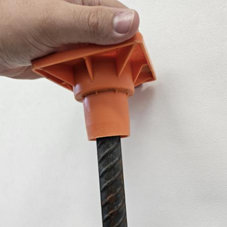
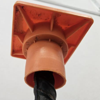
Figure 7 shows (a) side view and (b) bottom view of a rebar end cap being installed.
1.3 Installing and Removing Rebar End Caps
When installing rebar end caps on the end of the vertical rebar, each manufacturer has guidelines to properly install their rebar end cap [7-10]. These installation instructions are typically an 8.5 in. x 11 in piece of paper, and they can be found in the packaging with the rebar end cap directly shipped from the manufacturer. However, some local material suppliers may repackage these rebar end caps and leave out the instructions. These installation instructions can also be commonly found online at the manufacturer’s website. For most manufactures installation instructions have been to use the internal fins of the rebar end cap to be secured around the end of the rebar as shown in Figure 7a. The middle of the rebar end caps should be pressed firmly onto the end of rebar. This involves the vertical rebar being inserted onto the middle of the internal fins within the rebar end cap as shown in Figure 7b. Also, the end of the rebar should be fully inserted into the end cap until it comes into contact with the bottom of the impalement steel. Therefore, the rebar end cap should continue to be forced down onto the rebar until the end of the rebar comes in contact with the top plate of the cap. If the vertical rebar is only partially inserted into the rebar end cap, it may fall off and not protect from impalement. Each uncapped piece of rebar reported by OSHA can cost the offending company a fine amount. Once the vertical rebar is ready to be tied back into the reinforcement, these rebar end caps are removed and stored until they can be reused again.
When no longer needed for protection, rebar end caps are removed by pulling up on the top protective cover. Sometimes a hammer has been used to lightly tap tightly secured rebar end caps. These rebar end caps are then placed in various containers including a 5-gallon bucket, plastic storage containers, plastic contractor grade trash bags, or even back in the cardboard shipping box from the manufacturer. Then the rebar end caps in these containers will be stored until they are needed again.
1.3.1 Installation and Removal Rates of Rebar End Caps
The amount of time to install and then later remove these rebar end caps plays into estimating and managing a project. The installation rate of rebar end caps is the number of rebar end caps properly installed over time. And the removal rate of rebar end caps in the number of rebar end caps to be removed over time. Both of these have similar factors that control the production rate. Table 1 describes the key factors impacting installation and removal rate of rebar end caps. When installing the rebar end caps, the design of the rebar end cap and number of reuses effects how the rebar end cap will connect to the rebar. The spacing interval between vertical rebar will effect the travel time between installation and removal of each rebar end cap. Also, the container holding the rebar end caps such as a big cardboard box can sometimes be difficult to carry compared to a 5-gallon buck with a handle.
Table 1. Factors Impacting Installation and Removal Rates
| Factor | Description |
| Design of cap | Different design aspects of rebar end cap. |
| Cap reuses | Number of times a rebar end cap has been installed and removed |
| Spacing interval | Spacing interval between bar (1 ft., 2 ft., 3 ft., etc.) |
| Bar size | Size of rebar (#4, #5, #6, etc.) |
| Transportation container | Type of container used to store the caps (bucket, sack, cardboard box, etc.) |
Yet, estimating the time to install or remove these rebar end caps has not been researched [11]. A time study needs to be conducted to determine the standard time taken by a technician with reasonable skill and ability to perform the installation and removal of rebar end caps. By doing so this will help a contractor improve estimations behind labor costs and better prediction of time management behind rebar end cap installation and removal.
1.3.2 Reusage of Rebar End Caps
Reusing rebar end caps routinely occurs. Once a project requires these rebar end caps to be used, the rebar end caps will be taken out of storage and reinstalled on a project. These rebar end caps become damaged enough where they cannot be properly secured anymore. Unfortunately, tracking the reuse amount of these rebar end caps can be challenging due to them only being used temporarily on a project and then stored until they are needed again. Sometimes this is just a few days or weeks on the same project and other times, it may be months before another future project needs them. Furthermore, only a limited amount of research has been completed on the reusage of these rebar end caps [6].
1.4 Challenges with Rebar End Caps
1.4.1 Multiple Reuse
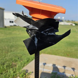
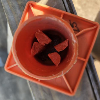
Many of the challenges associated with rebar end caps stem from improper installation of rebar caps. The rebar end caps should be pressed firmly onto the end of rebar. This involves the vertical rebar being inserted into the middle of the internal fins within the rebar end cap and continue to force rebar end cap down onto the rebar until the end of the rebar comes into contact with the top plate of the cap. One common installation scenario has been for the rebar end caps to be loosely attached or even sit crooked on the end of the vertical rebar. This is not the proper way to install rebar end caps. Therefore, the rebar end cap is not secure and there is a high probability the rebar end cap will eventually fall off the rebar and then leave the vertical end of the rebar exposed to workers potentially being impaled. Figure 8a shows a common method of using duct tape to secure the rebar end cap onto the end of the rebar. Once the rebar end caps are damaged as shown in Figure 8b, they will not be able to properly function. Some manufacturers state these rebar end caps should not even be reused if there is any noticeable damage on the rebar end cap [7-10]. Damaged or improperly installed rebar end caps will eventually fall off and exposing workers to an impalement hazard. Consequently, this leads to additional labor costs and delays due to unaccounted for reinstalling these rebar end caps.
(a)
(b)
Figure 8 shows (a) duct tape holding the rebar to the rebar end cap and (b) damage of the internal fins of a rebar end cap.
(a)
(b)
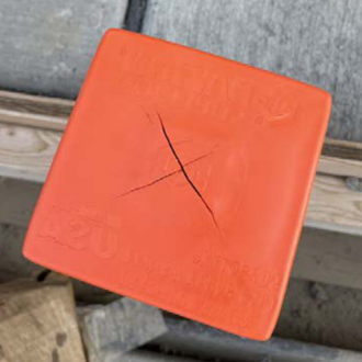
Figure 9 shows (a) complete fracture and (b) partial split in an x-pattern of the top protection cover.
1.4.2 Damaged during Installation
Sometimes a metal hammer or rubber mallet has been used during installation to force the rebar end cap onto the end of rebar. However, the rebar end caps will likely become damaged, which reduces the reusable service life of the rebar end cap as shown in Figure 9. Once the end caps have had any sort of damage, they will not be able to properly function. Some manufacturers state these rebar end caps should not even be reused if there is any noticeable damage on the rebar end cap [7-9]. Damaged or improperly installed rebar end caps will eventually fall off and exposing workers to an impalement hazard. Consequently, this leads to additional labor costs and delays due to unaccounted for reinstalling these rebar end caps. Also, each uncapped piece of rebar reported by OSHA can be fined and the offending company would be required to pay the fines.
1.5 Aim of Research
Limited research has been conducted to provide better insights into the installation cycle time, removal cycle time, and service life reusability of these rebar end caps. This study aims to compare multiple impalement rebar end caps. This involves both conducting an installation and removal time study and a service life reusage study. The purpose of the installation time study would be to provide valuable information about the time of rebar end caps to be properly installed and the time of rebar end caps to be removed. This will be conducted on rebar sizes #4 through #11. In addition, a service life reusage test will be conducted to determine how many times these different rebar end caps can be used. This research can give contractors better insights rebar end caps. It also has the potential to help provide more accurate estimates and reduce labor costs associated with reusing rebar end caps.
2.0 Experimental Methodology
2.1 Materials
2.1.1 Rebar End Caps
The three rebar end caps were used in this study as shown in Figure 10. The VariCap in Figure 10(a) will be compared to rebar end cap A in Figure 10(b) and rebar end cap B in Figure 10(c). These rebar end caps have the square end cap style. Based on the material information data sheet provided by the manufacturers, these three rebar end caps were recommended to be installed on reinforced steel bar sizes ranging from #4 to #11. Each of these caps meet the CAL/OSHA regulations for impalement caps in Title 8 under Section 1712 “Requirements for Impalement Protection” [5].

(a) (b) (c) Figure 10 shows (a) VariCap, (b) rebar end cap A, and (c) rebar end cap B.
2.1.2 Steel reinforcement
The steel reinforcement meets ASTM A615 “Standard “Specification for Deformed and Plain Carbon-Steel Bars for Concrete Reinforcement” [12]. All reinforced steel were deformed and had a yield stress meeting Grade 60. The bar sizes ranged from #4 to #11 as shown in Figure 11. All rebar lengths were cut to 1 ft.

Figure 11 compares a rebar sizes #4 through #11 (left to right).

Figure 12 shows a schematic of wall A and wall B.
2.2 Wall schematics
The testing area consisted of two walls on a concrete slab. The two walls were built with 2×4 lumber boards and ¼ inch plywood sheets. Figure 12 shows the schematic of the two walls spaced 8 ft apart. Each wall has a height of 4 ft and a length of 40 ft. The 1 ft steel rebar was installed onto the walls using high strength glue. Both wall A and wall B had different rebar size setups. For wall A, a quantity of 5 per bar size range from #4 through #11 was installed in each section of the wall as shown in Figure 12. In other words, wall A had 5 pieces of #4, 5 pieces of #5, etc. This wall A setup tested the reusability of the rebar end caps. For wall B, the bar sizes were all the same to measure the time of installation and removal per bar size. After testing for a bar size on Wall B was completed, Wall B was set back up with another bar size and then this bar size was measured for installation and removal.
2.3 Procedure for installing rebar end caps
According to the manufacturers guidelines for installation (7-10), the internal fins within the cap should be secured around the end of the rebar and the end of the rebar should be fully inserted into the end cap until it comes into contact with the bottom of the impalement steel. Following these manufacturers’ guidelines, the research team attempted to manually force the cap onto the end of the rebar. A twisting downward force of the cap onto the end of the rebar was used to get the internal fins to be secured around end of rebar and then the cap was pushed down until there was not room left. While a hammer has been possibly used on jobsites to force the cap onto the end of the rebar, this hammering can damage the cap and limit the reuse of the caps. Therefore, if the cap can’t be manually secured, it is considered a failure. This secured or non-secured status would be determined based off the kick test.
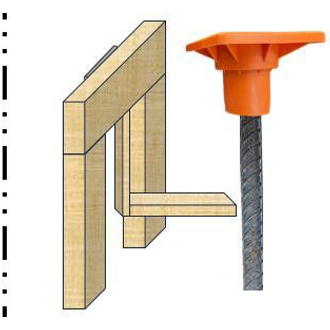
2.4 Kick Test
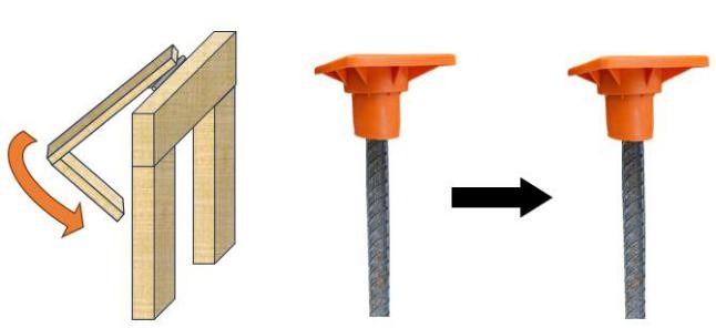
A test was needed to help highlight unsecure rebar end caps. Based off a novel prototype by others [6], the kick test was developed to mimic a foot of a person lightly kicking a vertical piece of rebar. The test apparatus was made largely from 1×4 lumber boards as shown in Figure 13. The frame of the apparatus has a height of 12 inches and a width of 12 inches. A hinge was installed connecting the frame to the plugger. This hinge provides the swinging motion of the plugger. To perform the Kick Test, the apparatus was installed adjacent to the row of vertical rebars and the plugger was aligned at the appropriate distance to be able to strike the rebar with the plugger. After installing a rebar end cap onto the end of the rebar, this test was operated as shown in Figure 13. The following steps are performed: a.) test apparatus is aligned on rebar; b.) plugger is released swings down to strike the rebar; c.) repeat steps a and b for 2 more times. Then record if the rebar end cap became secure or unsecure. The plugger was only allowed to hit the rebar 1 time per release. In other words, this plugger should be released 3 times and strike the bar 3 times.
(a)
(b)
(c)
Figure 13 shows (a) setup and alignment apparatus, (b) release of plugger, and (c) plugger striking the vertical rebar using the Kick Test.
2.4.1 Pass or fail criteria using the Kick Test
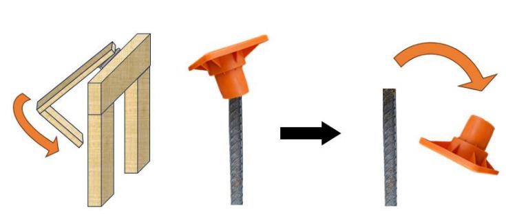
After the plugger strikes the vertical rebar three times, the operator will record if the cap is secure or non-secure. A non-secure cap is concluded when a cap falls off the rebar or becomes unstable when the plugger strikes the vertical rebar during any of the three strikes. If the cap does not fall of the rebar or doesn’t show signs of instability, then it is determined to be stable. Both of these scenarios are illustrated in Figure 14 (a) and (b).
(a)
rebar cap kick test b fail
(b)
Figure 14 illustrates Kick Test with (a) secure and (b) non-secure rebar end cap.
3.0 Results & discussion
Both a time study and service life reusability study were conducted on three different impalement rebar end caps. To ensure the rebar end caps were properly installed, the Kick Test was used to highlight unsecure rebar end caps. For the time study, the time to install and the time to remove the 3 rebar end caps were recorded. This was completed for rebar sizes #4 through #11. At least three different operators were used to measure the time and service life reusability. For the service life reusability study, three different impalement rebar end caps were each measured for the number of reuses per a specific rebar size. This was counted by the number of reuse cycles for installing and removing. For each size of rebar, there was five caps used. This was completed for rebar sizes #4 through #11. The results of these studies are provided in the proceeding sections.
3.1 Time Study: installation and removal of rebar end caps
Three different rebar end caps were used in this testing. Each was measured by the time required to securely install and then remove it. This was completed by at least 3 different operators using wall B. Installing these rebar caps were completed manually to get the internal fins of the rebar end cap to securely fit around the rebar end cap. To ensure the rebar end caps were properly installed, the Kick Test was used to highlight unsecure rebar end caps. The average time to securely install the rebar end cap per bar sizes #4 through #11 was recorded as shown in Table 2. Both Rebar end cap A and B had a longer duration of installation time than VariCap. As discussed in the experimental methods sections, no hammers were used in this study as this hammering can damage the cap and limit the reuse of the caps.
Table 2. Average Installation & Removal Time of Wall B (at 1ft spacing for 40ft)
| Bar | VariCap | Rebar End Cap A | Rebar End Cap B | ||||
| Installation | Removal | Installation | Removal | Installation | Removal | ||
| Size | |||||||
| (secs) | (secs) | (secs) | (secs) | (secs) | (secs) | ||
| #4 | 41.7 | 36.8 | 79.5 | 40.6 | 83.0 | 35.9 | |
| #5 | 40.0 | 33.5 | 95.8 | 35.7 | 102.7 | 36.3 | |
| #6 | 40.6 | 35.1 | 104.4 | 35.5 | 125.3 | 41.4 | |
| #7 | 40.8 | 35.1 | 117.0 | 33.6 | 149.4 | 38.3 | |
| #8 | 40.2 | 37.3 | 121.9 | 36.8 | 164.1 | 38.7 | |
| #9 | 45.0 | 31.2 | 159.2 | 33.5 | 181.2 | 38.3 | |
| #10 | 51.3 | 35.2 | 170.1 | 34.1 | 197.5 | 37.1 | |
| #11 | 57.3 | 36.8 | 178.2 | 40.1 | 208.3 | 43.1 | |
3.1.1 Installation rates
To apply these times in Table 2 to production rates, the time to install rebar end caps on the 40 ft wall was calculated in rebar end caps installed per minute. Figure 15 compares the three rebar end caps being installed within a minute. These values were average values of at least three operators. VariCap was able to install the highest quantity of caps. In fact, compared to the other two rebar end caps, the VariCap was able to be installed on two to three times as many pieces of rebar sizes #4 to #10. However, there was a downward installation trend of the VariCap from #9, #10, and #11 bars due to the bottom fins fitting tighter between the rebar and the inside neck of the rebar end cap. Yet, the Varicap was still able to be installed on more pieces of #11 rebar than the other two rebar end caps. The bar sizes for #4 to #8 with the VariCap had similar installation values, but #9 to #11 bar sizes did see a decrease and therefore had an impact on installation. Rebar end cap A and B had a decreasing installation rate for bar sizes #4 through #11. As the bar size becomes larger, both rebar end cap A and B wasn’t able to be installed as quick. As discussed in the experimental methods sections, no hammers were used in this study as this hammering can damage the cap and limit the reuse of the caps.

Figure 15 compares the average installation times for the three rebar end caps.
3.1.2 Removal rates
Again, to determine the removal times of these rebar end caps, Figure 16 compares how many rebar end caps can be removed within a minute. The removal times were similar for all three rebar caps. The times ranged from 58 to 77 caps removed per minute depending on the rebar end cap and bar size. The VariCap and rebar end cap A were able to be removed the quickest for all bar sizes. Rebar end cap B had the slowest removal time for #6 through #11 bar sizes. The bar size and type of rebar end cap did not play a major role in the removal times.

Figure 16 compares the average removal times for the three rebar end caps.
3.2 Service life study: reusage of rebar end caps
The service life reusability of 3 different rebar end caps were investigated using wall A. This 40ft wall contains a total of 40 pieces of rebar spaced at 1ft. There are five pieces of rebar per bar sizes #4 through #11 to test the reusability of each rebar end cap. One reuse cycle involves both the installation and removal of a rebar end cap. Installing these rebar caps were completed manually to get the internal fins of the rebar end cap to securely fit around the rebar end cap. To ensure the rebar end caps were properly installed, the Kick Test was used to highlight unsecure rebar end caps. As discussed in the experimental methods sections, no hammers were used in this study as this hammering can damage the cap and limit the reuse of the caps. Therefore, if the cap can’t be manually secured, it is considered a failure. Table 3 contains the average number of reuse cycles per bar size for each rebar end cap. This is also plotted in Figure 17. These reuse cycles are the average of 5 rebar end caps per rebar size.
Table 3. Average Number of Reuses for Each Rebar End Caps
| Bar Size | VariCap | Rebar End Cap A | Rebar End Cap B |
| #4 | >1000 | 100 | 80 |
| #5 | >1000 | 80 | 70 |
| #6 | >1000 | 60 | 50 |
| #7 | >1000 | 50 | 40 |
| #8 | >1000 | 30 | 30 |
| #9 | >1000 | 5 | 10 |
| #10 | >1000 | 5 | 5 |
| #11 | >1000 | 3 | 5 |

Figure 17 compares the number of reuses for each rebar end cap.
The rebar end cap B had reuse numbers ranging between 5 to 80 reuses depending on each bar size. The rebar end cap A was able to be reused between 3 to 100 reuses depending on bar size. These two rebar end caps perform similar to another research group [6]. VariCap was able to be reused 1,000 times. But testing was discontinued after 1,000 reuses due to this being considered excessive testing. The small bar sizes of #4 and #5 bar had the highest number of reuses for all the rebar end caps.
3.2.1 Rebar End Cap A Reusage
The rebar end cap A was able to be reused on average between 3 to 100 reuses depending on bar size. The small bar sizes of #4 and #5 bar had the highest number of reuses for all the rebar end caps. Figure 18 compares rebar end cap A being reused on a #5 rebar after (a) 10 reuses, (b) 20 reuses, (c) 80 reuses. The internal fins of this rebar end cap become damaged due to the friction and stress from the rebar. However, as shown in Figure 17, the reuse of rebar end cap A for bar sizes #9 through #11 decreased to 10 or less. An example of #10 rebar end caps after 3 and 5 reuses as show in Figure 19. A decrease of reusage occurs as the bar size increases. This is due to the internal fins becoming deformed and damaged as the bar size increases. These rebar end cap results performed similar to findings from another research group [6].
(a)
(b)
(c)
Figure 18 compares rebar end cap A being reused on a #5 rebar after (a) 10 reuses, (b) 20 reuses, (c) 80 reuses.
(a)
(b)
Figure 19 compares rebar end cap A being reused on a #10 rebar after (a) 3 reuses and (b) 5 reuses
3.2.2 Rebar End Cap B Reusage
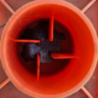
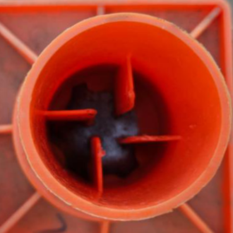
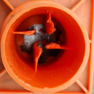
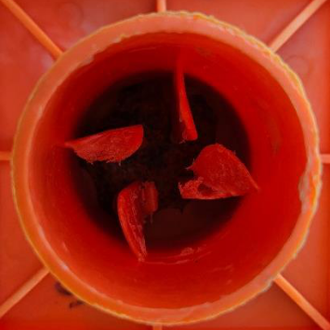
The rebar end cap B had the lowest reuse numbers ranging between 5 to 80 reuses depending on each bar size. The small bar sizes of #4 and #5 bar had the highest number of reuses for all the rebar end caps. Figure 20 compares rebar end cap A being reused on a #5 rebar after (a) 10 reuses, (b) 20 reuses, (c) 80 reuses. However, as shown in Figure 17, the reuse of #9 through #11 decreased to 10 or less. This is shown in Figure 21. A decrease of reusage occurs as the bar size increases. This is due to the internal fins becoming deformed and damaged as the bar size increases. Again, these rebar end cap results performed similar to finding from another research group [6].
(a)
(b)
(c)
Figure 20 compares rebar end cap B being reused on a #5 rebar after (a) 10 reuses, (b) 20 reuses, (c) 80 reuses.
(a)
(b)
Figure 21 compares rebar end cap B being reused on a #10 rebar after (a) 3 reuses and (b) 5 reuses.
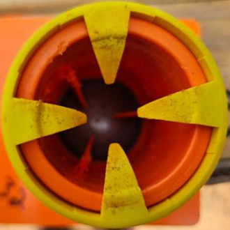
3.2.3 VariCap Reuses
Compared to rebar end cap A and rebar end cap B, VariCap had significantly more reuses. VariCap was able to be reused 1,000 times. But testing was discontinued after 1,000 reuses due to this being considered excessive testing. To support this, installing and removing a rebar end cap 1,000 times would be equivalent to almost 20 years of use based on assuming removal of cap once per week (52 weeks x 20 years=1,040 reuses). Figure 22 compares the VariCap being reused on a #5 bar after (a)100, (b) 500, and (c) 1000 reuses.
(a)
(b)
(c)
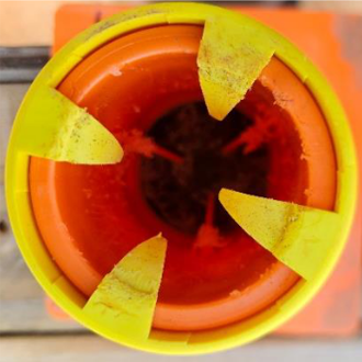
Figure 22 compares VariCap being reused on a #5 rebar after (a) 100 reuses, (b) 500 reuses, (c) 1000 reuses.
(a)
(b)
(c)
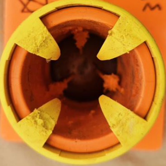
Figure 23 compares VariCap being reused on a #10 rebar after (a) 100 reuses, (b) 500 reuses, (c) 1000 reuses.
As shown in Figure 23(b), after 500 uses the yellow bottom fins of the VariCap became slightly deformed with bar sizes #9, #10, and #11. As the reuses increased, the yellow fins became more deformed. This deformation did not impact the secure fit around the rebar even after 1000 uses. However, if this cap were reinstalled on a smaller rebar size, then it is possible the cap may not securely fit on the rebar. As one possible solution, a technician could push the yellow fins with a finger to ensure the fins fit secure as possible to the rebar as shown in Figure 24. It is important to note this adjustment did not occur during any of the testing in this report.

Figure 24 shows a technician pushing the yellow fins with a finger.
5.0 Conclusion
Both an installation and removal time study and a service life reusage study were conducted on three different rebar end caps. Rebar sizes #4 through #11 were used on these studies. For the installation time and reusability studies, the VariCap was able to out perform the other two rebar end caps. The removal time study did not find a major change between the rebar end caps. The following conclusions were made:
Installation and removal study
- The installation times of VariCap had the shortest duration for bar sizes #4 through #11.
- Furthermore, VariCap for each bar size was able to be installed two to three times quicker than rebar end cap A or B.
- The bar size did impact the time required to install the rebar end caps, but the removal rate had similar trends between all bar sizes.
- Rebar end caps A and B had similar installation rates for each bar size. Both had a descending installation rate and slower installation time as the bar size increased.
- VariCap had similar cap installation rates for bar sizes #4 through #8 and then there was a decreased installation rate as the bar sizes increased in diameter.
- The removal time study did not find a major change between the rebar end caps or bar sizes.
Reusability Study
- VariCap was able to be reused 1,000 times on all bar sizes, but testing was discontinued after 1,000 reuses based on this being considered excessive testing. Reuses of 1,000 times would be equivalent to almost 20 years of use assuming removal of cap once per week (52 weeks x 20 years=1,040).
- Rebar end cap A was able to be reuses between 20 to 100 reuses depending on bar size. These two rebar end caps performance similar to another research group [6].
- Rebar end cap B had the lowest reuse numbers ranging between 5 to 80 reuses depending on each bar size.
- The bar size did impact the service life reusability of rebar end caps A and B.
- As the bar size increased, the number of reuses decreased for both rebar end caps A and B.
- For rebar end cap A and B, the small bar sizes of #4 and #5 bar had the highest number of reuses for all the rebar end caps.
Acknowledgements
The authors would like to thank the following undergraduate students for assisting with this research: Molly McCrary, Jonathan Hagan, Jace Busteed, Griffin Moore, and Jaggar Coulson.
References
[1] ACI Committee E703 “Contractor’s Guide to Quality Concrete Construction”, 4th Edition. American Concrete Institute (ACI). Farmington Hills, MI. 2018 ISBN: 9781641950473
[2] Kosmatka, S., and Wilson, M. “Design and Control of Concrete Mixtures.” 16th ed. Portland Cement Association. Skokie, Illinois. 2016.
[3] “Reinforcing Steel.” Subpart Q 1926.701(b), 29 CFR 1926 OSHA Construction Industry Regulations & Standards. Davenport, IA. 2019, pg 371.
[4] “Rebar Impaled Accidents”. Occupational Safety and Health Administration (OSHA). United States Department of Labor. Washington, DC (Searched on 7/28/2023)
https://www.osha.gov/ords/imis/accidentsearch.search?sic=&sicgroup=&naics=&acc_description=&acc_abstract=&acc_keyword=rebar%20imp aled&inspnr=&fatal=&officetype=All&office=All&startmonth=03&startday=07&startyear=2021&endmonth=03&endday=07&endyear=1984& keyword_list=&p_start=&p_finish=60&p_sort=&p_desc=DESC&p_direction=Next&p_show=20
[5] “Section 1712 Requirements for Impalement Protection”, Title 8 California Code of Regulations, Chapter 4: Division of Industrial Safety, Subchapter 4 Construction Safety Orders, Article 29 Erection and Construction. Section 1712, Division of Occupational Safety and Health. Oakland, CA. (Accessed
online on 6/14/2023) https://www.dir.ca.gov/title8/1712.html
[7] Hoover, Steven. Nefores, Spencer. “Rebar Impalement Safety”, Senior (Undergraduate) Project Report. California Polytechnic State University, San Luis Obispo, CA. 2020.
[8] “OSHA Rebar Cap: Technical Product Data Sheet.” OCM, Inc. Grayslake, IL. Accessed 5/27/2023.
[9] “Technical Data Sheet and Installation Instructions”. The J D Russel Company. Tucson, Arizona.
Accessed 7/31/2023 https://www.jdrussellco.com/wp-content/uploads/Impalement-Cap-Installation-BW-Flyer-PRINT.pdf
[10] “Technical Data Sheet” Dayton Superior. Miamisburg, OH. Accessed 7/31/2023
https://catalog.formtechinc.com/wp-content/uploads/pdf-front/1599756634137795194.pdf
[10] “Deslauriers Impalement Safety Cap” Deslauriers Inc. LaGrange Park, IL. Accessed 7/31/2023.
https://deslinc.com/mwdownloads/download/link/id/450/
[11] RS Means Building Construction Cost Data. “Reinforcing In Place Impalement Protective, Plastic, #4 to #9.” Line number 03 21 11.60 2750. 74th Gordian Group Rockland, MA. 2015 Pg 70.
[12] ASTM A615 “Standard “Specification for Deformed and Plain Carbon-Steel Bars for Concrete Reinforcement”. ASTM International. West Conshohocken, PA 2022.
Appendix A: Data from this Research
Table A1. Average Installation & Removal Time per Bar @ 1ft spacing for 40ft (caps per min)

Table A2. Number of Reuses for Each Rebar End Caps

Appendix B: CAL/OSHA
344.90. Impalement Protection. Specifications and Testing Criteria
Note: from the CAL/OSHA Website (Accessed online on 6/14/2023)
(a) Scope: This section governs the testing of manufactured protective covers designed to prevent accidental impalement from exposed reinforcing steel (rebar) or other similar projections.
(b) Effective Date: This section applies to all protective covers manufactured on or after October 1, 2000.
(c) All manufactured protective covers used as protection against impalement for workers at grade or the same level as the projection shall:
(1) Pass the drop test described in subsection (e) of this section, except that the drop height may be reduced to 7 1/2′.
(2) Meet all other applicable requirements of section 1712 of this Code.
(d) All manufactured protective covers used as protection against impalement for work performed at levels not to exceed 7 1/2′ above grade shall:
(1) Have a minimum of 4″ by 4″ square surface area, or if round, a minimum diameter of 4 1/2″. Troughs shall be at least 4″ wide.
(2) Pass the drop test specified in subsection (e) of this section.
(3) Meet all other applicable requirements of section 1712 of this Code.
(e) Manufactured protective covers shall be able to pass the following penetration tests, as verified by a person, firm, or entity with appropriate registered-engineering competence, or by a person, firm, or entity, independent of the manufacturer of the subject protective covers, with demonstrated competence in the field of such evaluation.
(1) Protective covers for rebar shall be tested for penetration by dropping a 250-lb. bag of dry sand (less than 10% moisture by weight) onto the subject protective cover from a height of 10′. The 10′ shall be measured from the bottom of the bag to the top of the protective cover.
(A) The sandbag shall be generally round, and shall have a circumference of 36″ to 42″. When filled with 250 lbs. of sand, the bag shall be tightly closed by use of crimping, drawstring, or twisting at the top level of the sand so that there is little extra room in the bag to allow the sand to shift. The bag shall be constructed and reinforced (as necessary) with material, which will not rupture or be penetrated by the protective cover for rebar.
(B) The protective cover for rebar shall be installed over the sheared end of a piece of #4 rebar. The rebar shall be mounted on a support with 6″ of the rebar projecting vertically above the surface of the support. The support shall be of such height and width that it shall not interfere with the falling sandbag, and shall allow the full initial impact of the sandbag to be borne by the protective cover.
(C) The drop test shall be repeated three times, using a new protective cover for each test. One drop test shall be performed with the protective cover sitting squarely on top of the rebar; the other two drop tests shall be performed with the protective cover sitting at the maximum angle out of square (out of level) that the protective cover will permit with its stabilizer vanes/fins removed.
(2) Protective covers for projections or equipment other than rebar, (such as lightning rods,) shall be tested in the same manner as protective covers for rebar, except that protruding equipment which is
normally installed with a protective cover as a single unit may be tested as a unit, using the equipment in lieu of the rebar.
(3) Rebar troughs shall be tested for penetration by dropping a 250-lb bag of dry sand (less than 10% moisture by weight) onto the subject trough from a height of 10′. The 10′ shall be measured from the bottom of the bag to the top of the protective cover.
(A) The sandbag shall be generally round, and shall have a circumference of 36″ to 42″. When filled with 250 lbs. of sand, the bag shall be tightly closed by use of crimping, drawstring, or twisting at the top level of the sand so that there is little extra room in the bag to allow the sand to shift. The bag shall be constructed and reinforced (as necessary) with material, which will not rupture or be penetrated by the protective cover for rebar.
(B) The trough shall be installed over the sheared ends of three pieces of #4 rebar. The three pieces rebar shall be mounted in a straight line, 24″ apart, on a support with 6″ of each piece of rebar projecting vertically above the surface of the support. The trough shall be 72″ in length, and shall be centered over the three pieces of rebar so that 12″ of the trough extends beyond each of the outside pieces of rebar.
(C) The drop test shall be repeated four times, using a new trough for each test. The sandbag shall be dropped: (i) once with the trough level and the sandbag centered over the middle piece of rebar; (ii) once with the trough level and the sandbag centered over one of the end pieces of rebar; (iii) once with the trough tilted (at the maximum angle allowed by the design) with the sandbag centered over the middle piece of rebar; (iv) once with the trough tilted (at the maximum angle allowed by the design) with the sandbag centered over one of the end pieces of rebar.
(4) Other methods for penetration testing may be substituted for those set forth in this section where acceptable to the Division as being equally effective.
(f) Each manufacturer, or other person or entity reselling or distributing manufactured protective covers, shall furnish the ultimate user of the protective cover with instructions regarding appropriate use of the protective covers. The instructions, written in English, shall include at least the following:
(1) Instructions as to whether the protective cover is designed for use at grade or above grade.
(2) A statement indicating the maximum height of fall that the cover is designed to protect against impalement, but not to exceed 7 1/2′.
(3) Installation instructions.
(4) Instructions regarding the inspection and/or use of damaged or defective protective covers. The effects, if any, of damaged stabilizer vanes/fins shall be included in this instruction.
(5) Any other instructions deemed necessary by the manufacturer regarding the use of the protective covers.
(g) Each employer whose employees use or work around or above protective covers shall inform its employees of the content of the manufacturer’s instructions. Such information shall be provided to employees in a manner that allows them to understand the appropriate use of protective covers and the hazards associated with impalement.
(h) Marking – Each protective cover shall be marked with the following information:
(1) Model Number or Trademark.
(2) California Approval Number as issued pursuant to Sections 1712 and 1505 of this Code.
Technical Report Documentation Page

Disclaimer
This research was funded through VariCap LLC. The contents of this report reflect the views of the authors who are responsible for the facts and accuracy of the data presented herein. Oklahoma State University does not endorse products or manufacturers. Trade and manufacturers’ names appear in this report only because they are considered essential to the research conducted in this document.